
MakeraCAM
We learned how to use the Makeracam software. I collaborated with some classmates on the following workflow on how to use the CNC machine and MakeraCAM software:
Preparing Design:
Open new 3D project
Set material to PCB: Edit→Material→PCB
Set dimensions: X = 127mm, Y = 101mm, Z = 1.7mm
Download the following files from Fab drive: (blue folder named Dubick) Resistance1-F_Cu.gbr, Resistance1-PTH.drl, Resistance1-Edge_Cuts.gbr
Import each of these files in MakeraCAM:
File→Import PCB→Downloads→”File”→Open
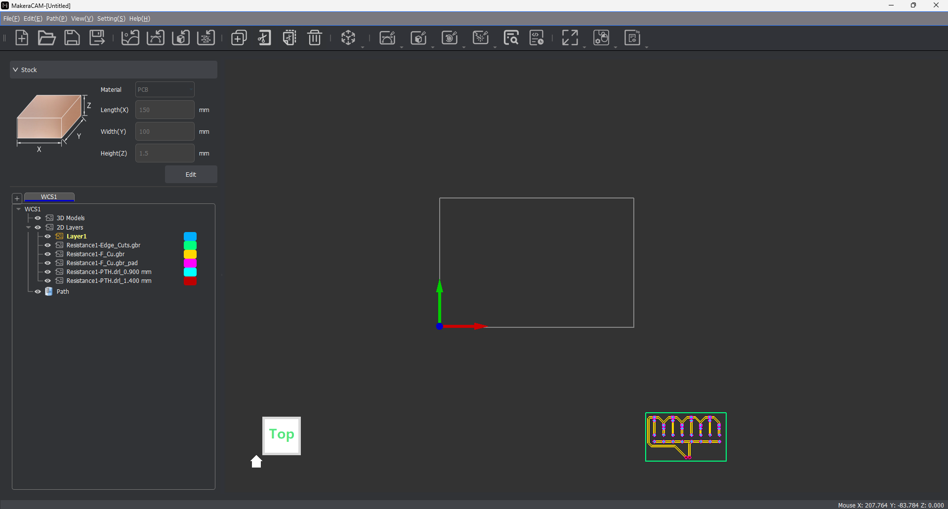
Below is a picture of the MakeraCAM software once all three KiCAD folders are uploaded:
Anchor lower left corner:
Select whole design (highlight over everything)
The software makes the paths look like this:
Click “m” key
Select lower left corner in “Anchor” diagram at the top of new pop up (in top right corner of screen)
Under “Location” in pop up, set X to 6 and Y to 6 (offsets design from very edge of material)
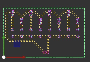
Design should have moved to align with axes given
Paths:
Under “2D Layers” menu, hide (eye with red cross through): Resistance1-F_Cu.gbr_pad, Resistance1-PTH.drl_0.900 mm, Resistance1-PTH.drl_1.400 mm
Select 2D Path (in tool bar)→2D Pocket
Select whole (visible) design
Set “End Depth” to .05mm
Add tool x2
8mm Corn
.2mm*30Engraving(Metal)
Calculate
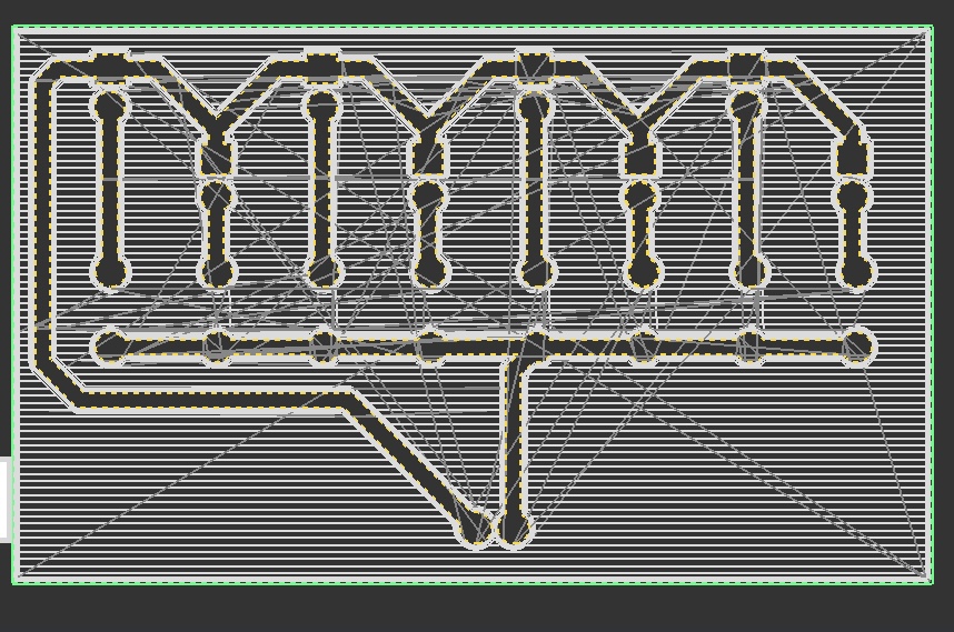
The paths toolpath, once created, looks like this:
Drilling holes:
2D Path→2D drilling
Under “2D Layers” menu, hide (eye with red cross through) all but file with holes to drill
End Depth: 1.7mm
Add tool: 8mm Corn
Calculate
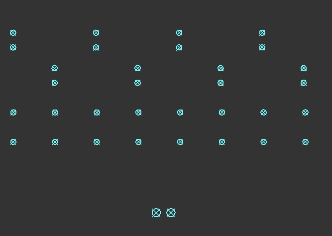
The holes toolpath, once created, looks like this:
Outside cut:
2D Path→2D Contour
Under “2D Layers” menu, hide (eye with red cross through) all but file with outside cut (Resistance1-Edge_Cuts.gbr)
End Depth: 1.7mm
Strategy: Outside
Tabs: Custom
Tab Shape: Triangle
Select “Add”
Click 3 places on outer edge (spaced fairly evenly apart)
Add tool: 8mm Corn
Calculate
Path→Export→Export OR if you want to edit file on milling machine’s computer, File→Save As, save file in downloads with .mkc format (file-type)
Upload file to your folder in Fab google drive
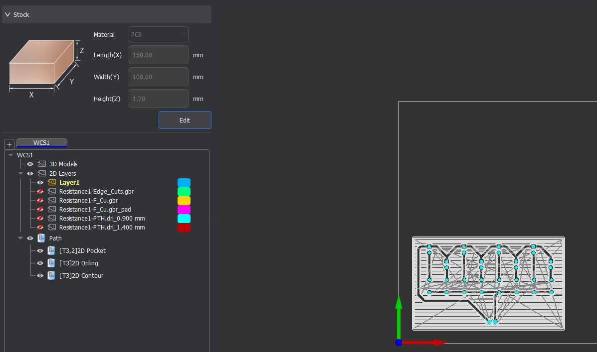
I saved the toolpaths I created in MakerCAM by exporting it as GCode file, and also saving the file as a .mkc file so I could bring that up on the computer when I milled the board. Below is a picture of the toolpaths and layers in Makeracam after all of these steps have been followed:
Milling Design:
Installing material:
Slightly loosen (not remove) all bolts in machine bed except the 3 that are fully within the metal jig/holder (use screwdriver on right side of machine)
If copper board already on bed with design milled into bottom left corner, remove and reorient if possible or else replace
Orient PCB board on CNC machine so that your design will fit in bottom left corner (as it was displayed on Makera CAM)
Adjust rectangular metal holders near middle of bed (keep bolts where they are, slide and rotate rectangular piece) to be able to slide material under loosened bolts, and then do so
Move/rotate both rectangular metal back so that short end of rectangle with slot aligns with material (holding it down)
Screw all loosened bolts down fairly tightly (securing material, not overly tight)
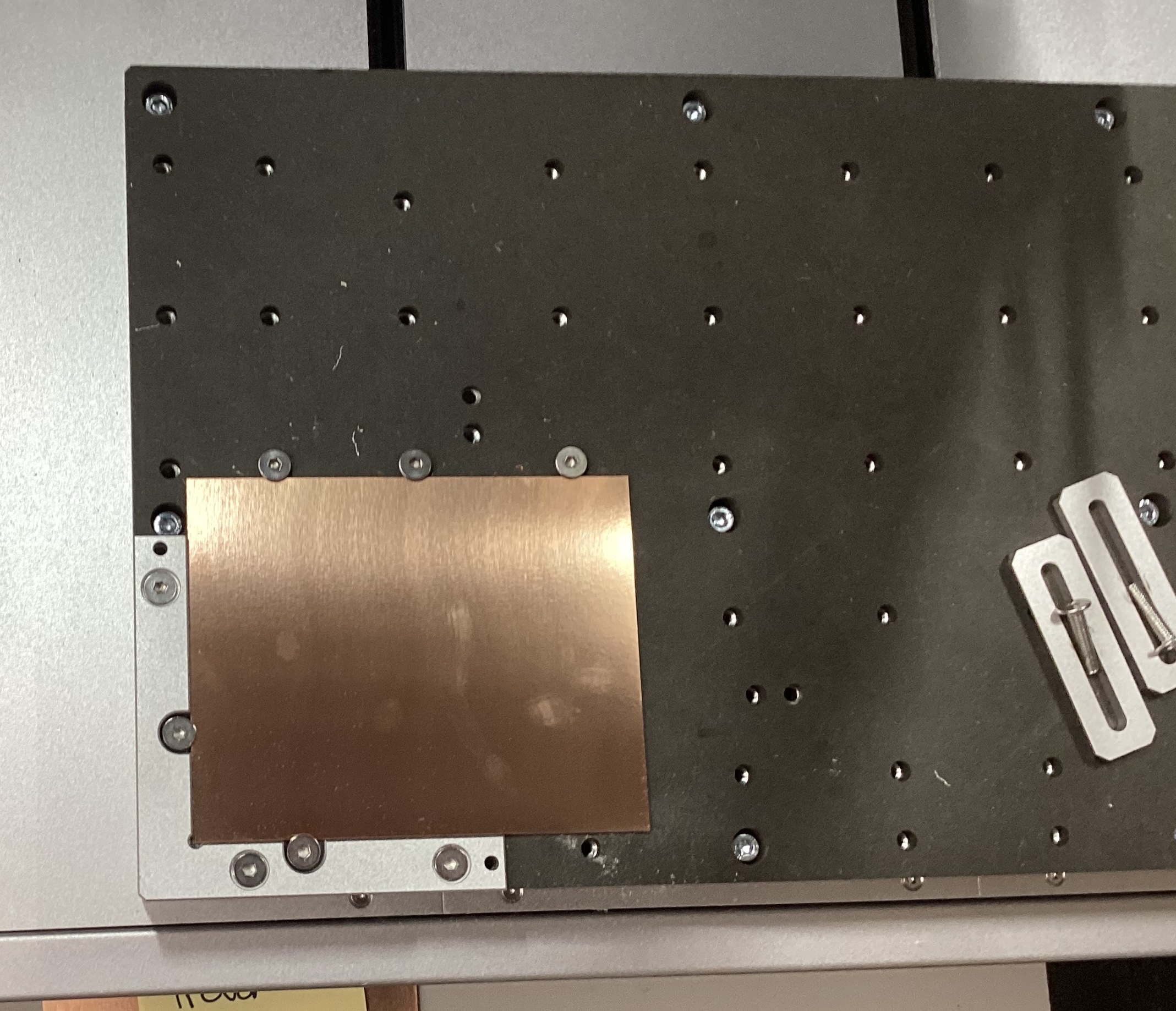
Once the board has been installed correctly, it should look like this:
Running file:
Download gcode.nc file from Fab google drive
Open Cavera Controller
Open file (top left corner) → Upload File → (should be in Downloads) select your gcode file (yourfilename.nc) → “Upload & Select”
Idle (top left) → COM Port ___ (some number)
Additional settings (top right dropdown) → Display Manual Controls → Home
Tool status → ensure Voltage>3.6V
Second most right option on bottom bar → select (check) auto vacuum + select (check) auto-levelling; select Run
Machine should touch down at 25 points on material and then file should run (whole design should be automatically milled)
Below is a picture of my milled board:
.jpg)
I did not face many challenges in this project. The only small one I did face was the original dimensions of the board we were given. As I went to mill my board, I was told that we had been given dimensions that did not actaully align with the baord we were given.I simply had to go back into the MakeraCAM software and change the board dimensions I had put in orignally. I then redownloaded all of the files. The dimensions and files above are correct.
This project and learning how to use the MakeraCAM software will be extremely helpful later on. I now have the skills to both create and mill a board, which I will definitely do in the future. I also know how to use this specific software, as the FABLab had been using a different software before.