
Topography - Mountain Range Project
After working with MakeraCAM to mill a PCB board, we learned how to mill other materials, such as wood. For this project, we made a topography map.
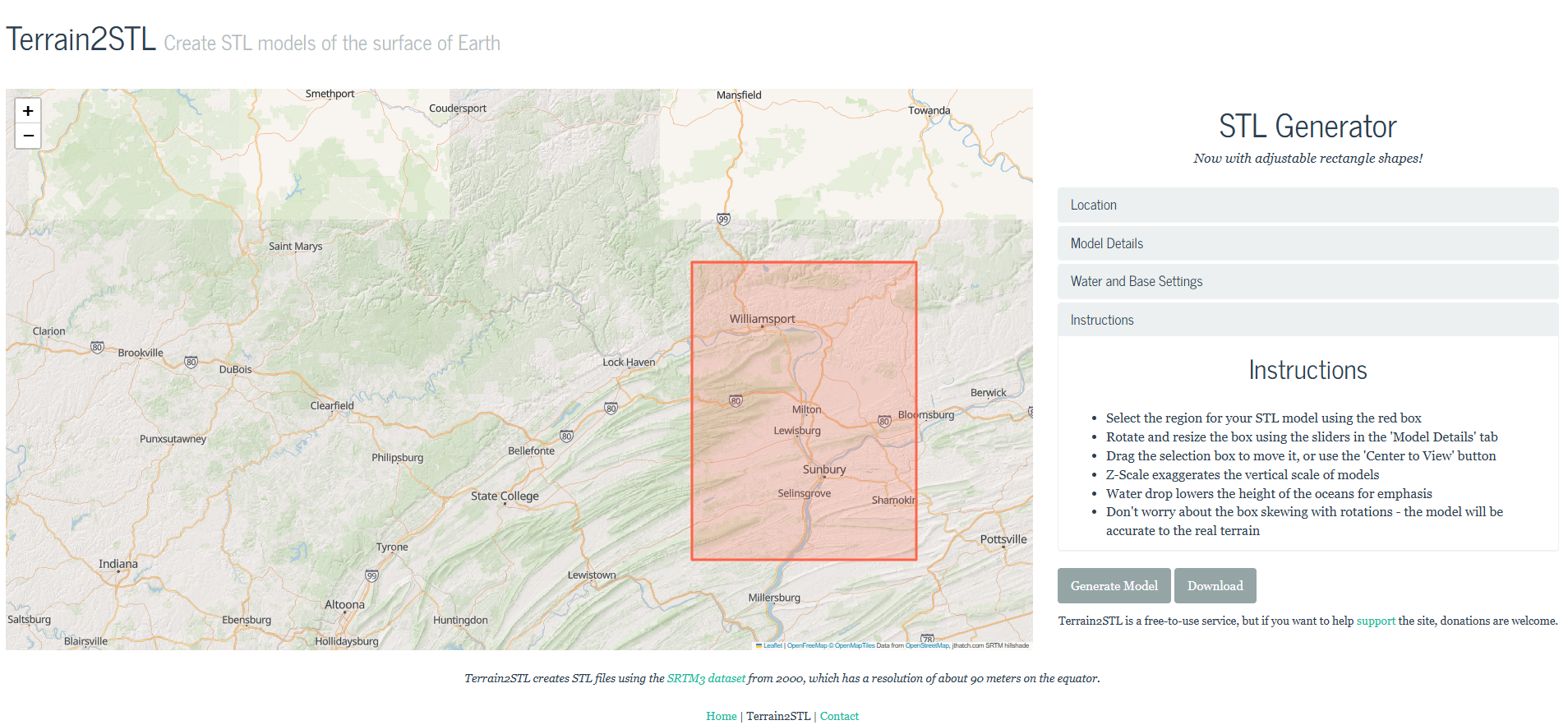
We started off by visiting this site called “Terrain2STL.” I decided I wanted my map to be of Lewisburg, Pennsylvania, where I will be going to college. I zoomed in on this portion of the map and changed the box area. I found that the location that I wanted was: Latitude: 41.4023 Longitude: -77.2358. Below is a picture of the website with my selected area, highlighted in the red box.
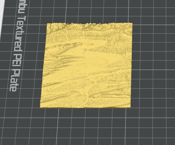
I saved it as an STL without changing any of the “Model Details” and sent it straight to Bambu Studio. When I opened the file, I could not make out any of the mountains or any part of the river. I went back to the site and raised the vertical scaling all the up, to level 4. When I sent it to Bambu as this .mf file, it appeared in Bambu how I wanted it to print, featured below.
And after printing, it looked like this:
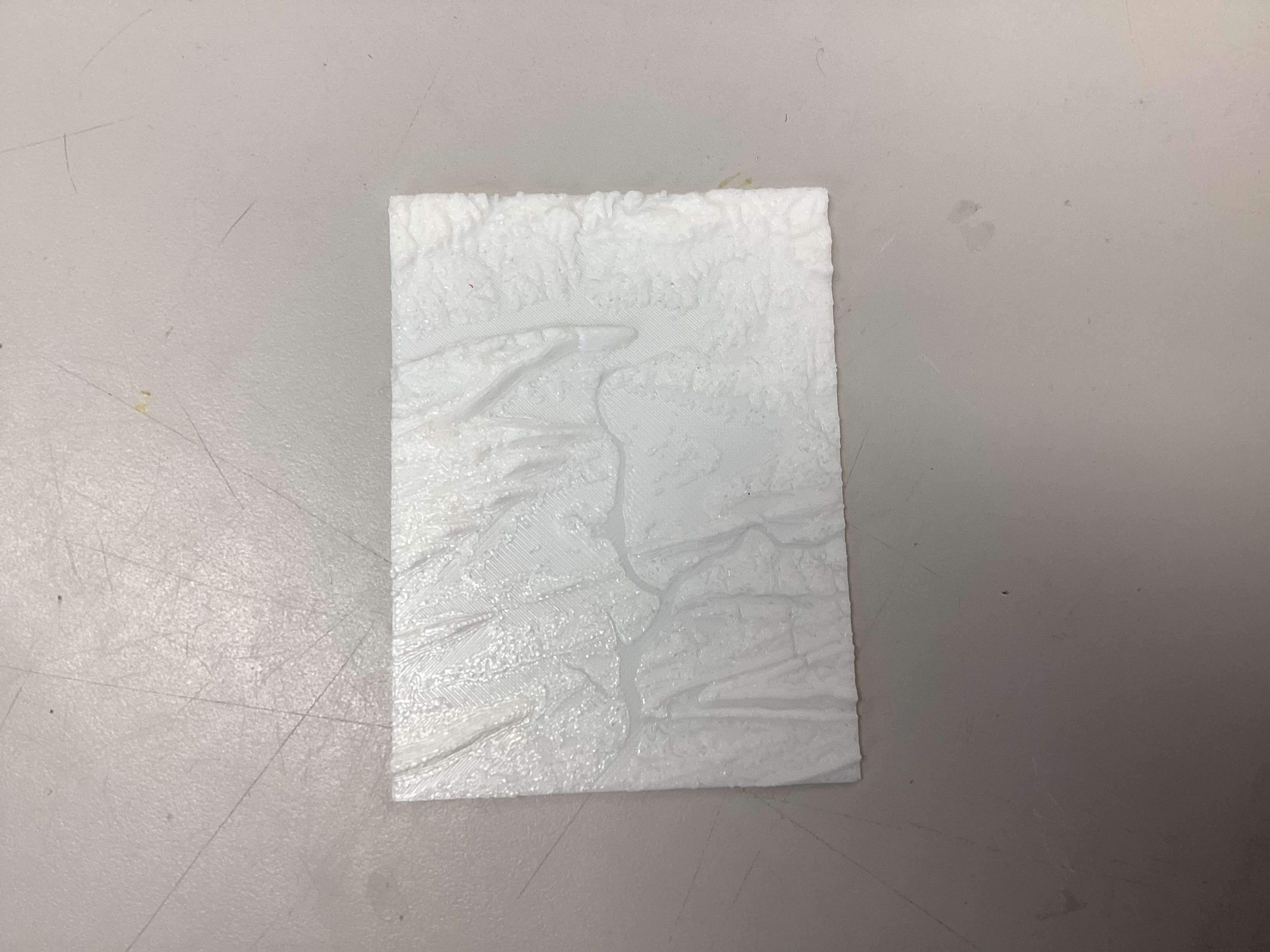
It came out how I wanted, so I moved on to carving the design with MakeraCAM software and the Carvera CNC machine.
I first created a new file in Aspire. I set the “Job Type” to “Single-Sided.” I set my “Job Size” to width (x): 2.5 in, length (y): 3.5 in, and height (z): 1.0 in, which matched my block of wood. The X axis is to the right and left of the bed, while the Y axis is to the back of the Carvera machine when looking at the bed.
I set the thickness (Z) and the “Zero Origin” to:
Z Zero Position: Material Surface (top) and the XY Datum Position: Bottom Left.
I then imported my 3D STL model. I went to the Modeling tab and clicked the “Import a Component or 3D Model” icon to import my STL file. I set the “Initial Orientation” to “Top.” I adjusted the model’s width, height, and depth to the lengths I used previously. I then used the “Lock” icon to fix the X, Y, and Z sizes so they would stay in the correct ratio. I applied this and centered the model. Next, I used the slider bar to keep my STL above the purple horizontal cutting plane so it would be cut correctly.
I then started to create the toolpaths. I started with the “Roughing Toolpath.” I set the material to Hardwood and selected the 1/8” end mill tool. I named this toolpath and calculated it. I then created the “Finishing Toolpath,” selecting a small 1/8” ball-nose bit; I named that toolpath and calculated it. Next, I created the “2D Roughing Toolpath,” setting the “Start Depth” to 0 and the “Cut Depth” to 0.5. I then selected a large 25 mm flute end mill (3.175 mm), named it, and calculated it.
I saved this file as this .crv file. I then clicked “Save Toolpaths,” saved all of my toolpaths, chose my machine as the “Carvera Desktop CNC Machine,” and selected the post-processor “Carvera ATC (mm).” This produced this .gcode file.
I went over to the computer attached to the Carvera CNC Machine. I used the same workflow for use of the CNC machine as I did for my MakeraCAM project. I placed my wood block into the CNC machine and tightened it with sturdier screws than I had used with the PCB. I installed the bottom flat bracket before adding and tightening the top triangle-shaped bracket. After installing my wood block into the CNC machine, I uploaded my .gcode file to the computer and homed the machine. I then previewed all of my toolpaths, which looked like this in the MakeraCAM software:
.png)
I then ran the job.
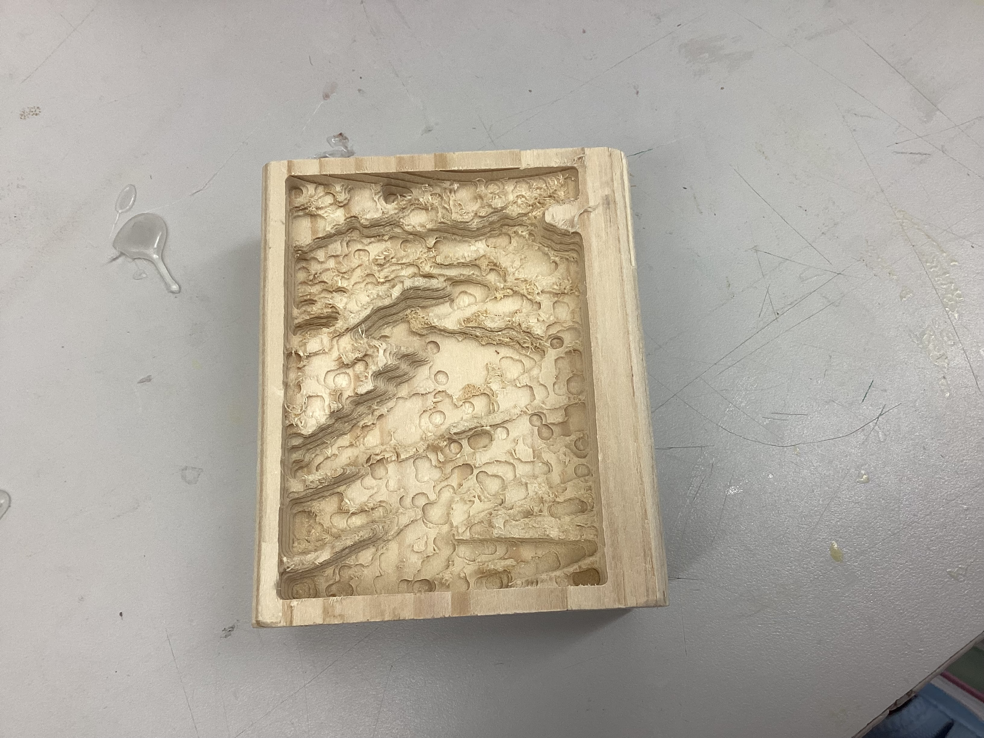
A very important problem I faced was that, as the CNC machine started to run, it began by tracing a red light over the area to be carved. I watched and realized that the red dot traced over some parts of the metal machine. I quickly paused the job and realized that I had not set the “Work Origin” to (6,6); it remained at (0,0) and would therefore have milled into the machine if I had not stopped it. I reran the job with the corrected origin, and it came out like this:
Conclusion: This project taught me that having the ability to visualize what will occur is very important. The machine’s tracing feature ended up saving a very costly fix. Also, in Aspire, there is a toolpaths preview that shows where the machine will mill the toolpaths, and gave a preview of how it should turn out. These previews help prevent problems and guarentee the outcome will be what you want. This project taught me the skills to use MakeraCAM and the Carvera machine itself (furthered my knowledge), as well as the Aspire software. My new knowledge of milling will definitely be helpful for future projects.